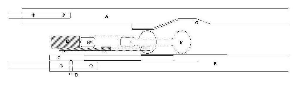
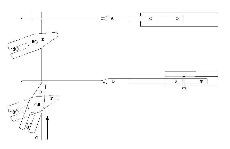
The manual to Pedal coupler mechanism used in the Apollo organ is not described in Audsley's "Art of Organ Building". It is a mechanism which operates faltlessly, and is perfectly adapted for use in reed organs. Its operation is described: Rods A and B are attached to the rear end of the manual keys which are slotted in their sides to accept the flat rods which are also screwed. The rods extend through a jumper rack containing 30 (one for each pedal note) verticle stickers C, which move in the direction indicated by the arrow. To each sticker is pivoted two levers indicated at D and E. Lever D is shown in the engaged position, and when the sticker C rises with the depresseion of a pedal key, it will push on the rod B and raise the rear end of the lower key. Lever E is shown in the disengaged position, when the stciker C rises, the lever E will have no effect on the rod A. Both levers D and E pivot about the points H H. The lever F is included to illustrate the change in position between the levers in the "on" and "off" positions. To engage and disengage the levers, the rods G G G are moved also about the point H H on the jumper-rack frame (not shown).
The rods G G G are connected to the corresponding stop registers via simple linkages. The couplers can be engaged and disengaged when the pedal keys are depressed. The ends of the levers D and E are covered with felt where they engage with the rods A and B. Adjustment is rather crude, but is obtained by slightly bending the rosd A and B so they are affected correctly.
The Manual Octave Coupler
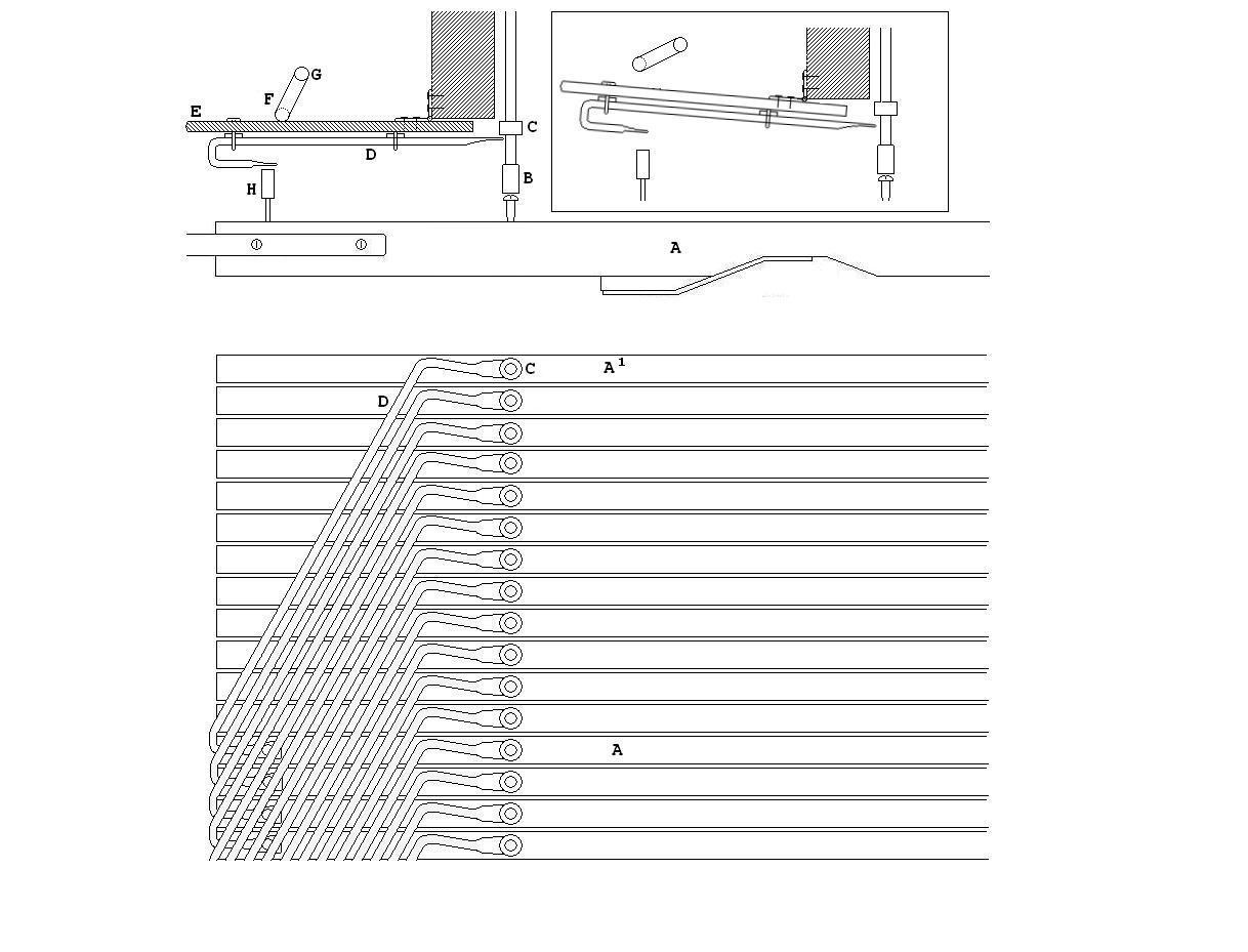
Diagram showing Swell Octave Coupler.
The Swell octave coupler is accomplished by metal rods D, which are laid diagonally above the rear end of the swell keys. The rods link each note with the note an octave, or 12 keys above. The mechanism is fairly straight forward, and very reliable. The Swell key, A, directly pushes the sticker, B, which opens the swell pallets. Behind the stickers, each key (save the top octave) has an adjustable button H, which engages with the octave coupler mechanism. The mechanism is brought into play by a linkage from the stop register to the cranked rod at F which turns about the point G. This presses on the stock E which carries the coupling rods, D. When the rod is lowered onto the button H, then depreing the key will cause the button to push the rod D, which revolves and lifts the coupler button, C, which is associated with the sticker of the note 1 octave higher.
The second illustration shows a section of the coupler rods over the keys. When the key, A, is pressed, the rod D, is caused to revolve slightly, lifting up the coupler button, C on the note which is played by key A 1.
This mechanism differs from the manual and pedal couplers in that it does not act on the key itself, but rather, the action. Because of this, when the swell octave coupler is drawn, the keys 1 octave higher will not appear to go down, the weight of the action is simply taken off them by the coupling rods, but they will not drop due to the weight of the action of the notes exactly one octave higher which, when the coupler is drawn, will obviously be resting on them. This is not true for the top octave, whose keys do drop when the below octave is played, because there are no higher notes coupled to this top octave.